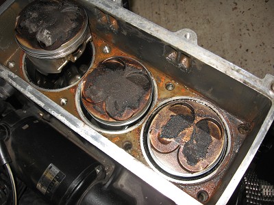
New head and Hi comp pistons. The last valve clearance check on the Speed Triple the inlet valves on a couple of them were down to about 2.30 shim thickness. The inlets are known for being the ones that sink into the head, symptoms can be bad cold starting a backfire and less than perfect running. The seat in the head is normally ok it’s the valves that wear.
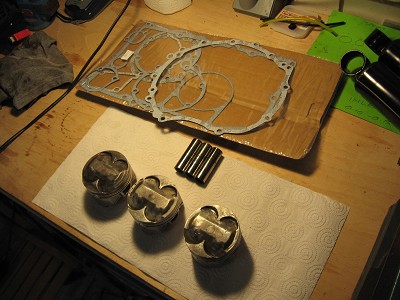
New valves is the answer so I knew some head work was on the cards, whilst I was going to be in there I’d been hatching a plan for some time to install some Hi comp pistons…the Daytona 750/1200/SuperIII, Trident 750 were all fitted with these and there is no further work required to get them to work, they are a plug and play part as it were.
They have a raised piston crown that creates more squish of the fuel air mix in the combustion chamber..hence more compression, this gives you a bigger bang and more power anywhere between 7-10HP depending on how well you bike is set up.
It is advisable to replace the gudgeon pins when doing this as history has shown that they can be prone to oval, so I ordered up new pins the clips that secure them, new head bolts, head gasket and piston rings. Head bolts and rings can be reused if all still ok but I didn’t want the faff so just got the whole lot to make sure I was not going to be held up.
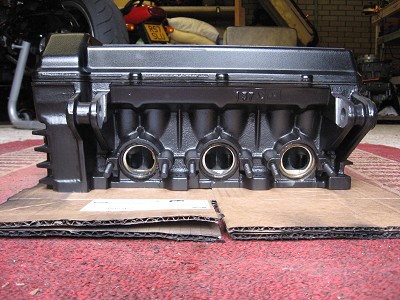
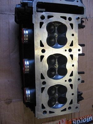
Ivan at National Triumph (top bloke and valuable resource of knowledge and parts) had some Daytona 750 pistons and did a fair price for me. A little while later luck fell through the door (again an Ivan part) in the shape of a NOS (new old stock) head complete with cams, valves, cam cover, gasket and exhaust gaskets. The whole thing was ready to fit! However it was grey so had to be painted and I used some PJ1 Black engine paint which has done a good job. The storage over the years hadn’t been too kind to the head and the cam cover was dinged in a few places and a lump missing from one of the fake cooling fins etc so a bit of a clean up was due
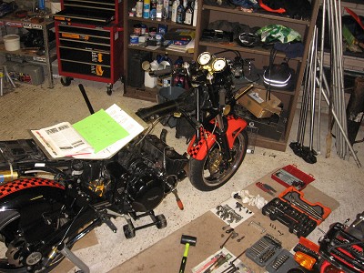
OK to work…a lot of stuff comes off for this but the lump can stay in the bike so it’s off with tank, carbs, coils, radiator and exhaust, engine cover for the crank position sensor then cams out and the two top engine mounting bolts. Now you can get to the head bolts whilst supporting the engine under the sump with a jack.
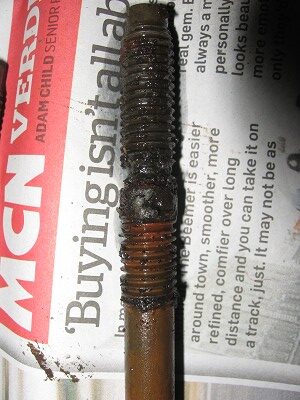
I used a 1/2inch sml breaker bar and a short bit of scaff pole to start them off working in a criss cross from the outside in. The head bolts are quiet long and sit in the coolant jacket around the piston liners, if the coolant has not been changed over the years or someone has raced it and used water only the head bolts can corrode and potentially break off in the head !!!! Mine were border line and was lucky with one that was deffo on the way
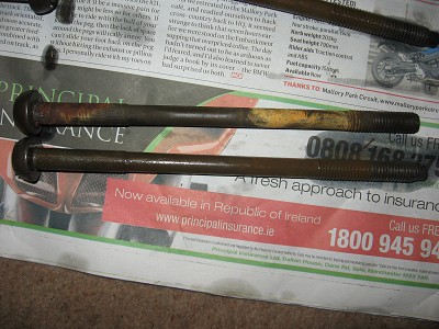
One of the center bolts fouls the frame, it’s too long to remove in the space between the engine and the frame headstock .I found slightly dropping the jack a little gave me just enough room to wiggle it out but it is very very tight ! The next challenge is the lift the head off. Hitting it with a soft faced mallet to unstick it and then lift up and out, be aware that there are locating dowels in the head that are steel and protrude either up or down depending which side they stick to (the head or the crank cases). You don’t want to damage the gasket face between head and engine with your cack handed wrestling of the head out of the bike !!!
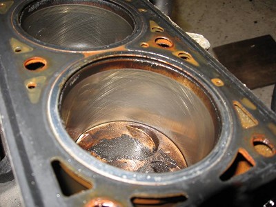
The coolant cavity around the piston liners will still have some coolant residue in there. Once the gasket is off mop it out as best you can, and start a clean up of area I used a gasket scraper to clean the top gasket face and lots of paper towel.
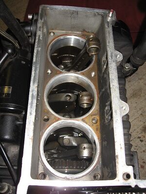
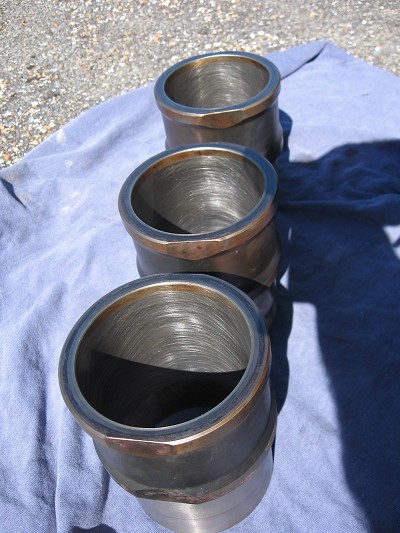
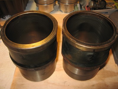
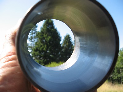
The next step is to remove the liners over the pistons, number them as you do so with a marker pen so you can replace them back in their original order You maybe lucky and the liners are loose and you just lift out but mine were stuck.
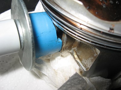
A handy tip from Clive Wood is to use the two plastic handles of screw drivers as a lever under the top lip of the liner levering against the top gasket face of the engine. Leave the middle one in while you do the outer two as this allows some captive space for you to lever in, once the outer two are free you can leave them in the lever the middle one out.
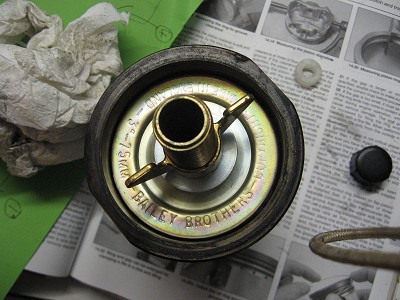
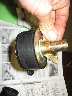
I did research for other ways of removing sticking liners and one was to use a drain bung and fab up a slide hammer to fix to it. I did get as far as sourcing one but thankfully never needed it but here is a couple of pics so you get the idea
Next challenge is the remove the gudgeon pin clips in each side of the piston, I bent a split pin in the vice to act as a hook. Stuff the cavity of the engine with towel as you don’t want these pinging out and dropping into the crankcase !!!
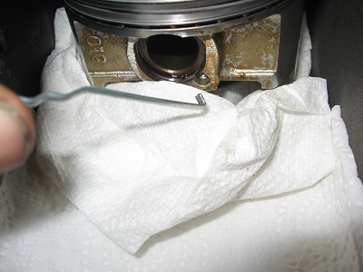
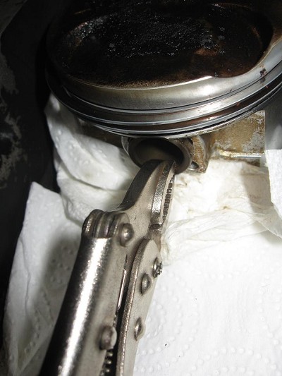
The pins wear and create a slight lip in the piston where the clip retains them. This is a bit of a pain as you have limited room to work in and they need something to force them over this lip so you can grip them and wiggle out.
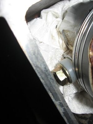
You will need to use a large socket on the nut at the end of the crank with the timing plate on it as you did when turning the engine over for valve checks. Dropping the ctr piston will allow you room to draw the pins out of the outer two, then raise the ctr one to work on while the outer two are dropped. I had to fab up a make do puller to get them moving
Once everything was out I could clean out the head bolt holes in the crank case. I used cotton buds to soak up any coolant then compressed air to give them a blast out making sure I’d got paper towel down the holes in the crank case for the liners and con rods
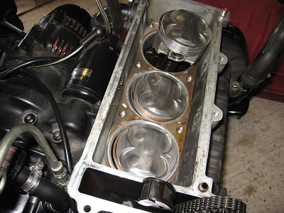
I popped the hi comps in with new pins and clips and rings. The ring gaps are offset against around the piston as per the manual. This is to try and get the best compression from them.
Then sealed the clean liners with Blue Holymer and seated them over the pistons. You won’t need a tool to compress the rings as there is a slight champher to the bottom on the liner that helps funnel them together
I’d oiled the inside of the liners and also again when I had them in place over the pistons. Now to get the new head on, so on with a new head gasket, (again being careful not to damage anything with the locating dowels). Seat the head and lightly tap into position. Slide the head bolts in and have the aforementioned struggle with the middle one again ! I just got it in by playing with the jack !!!!!
Tighten them in order criss crossed from the outside in first all to hand tight, then all to 20NM then all to 27NM and finally a 1/4 turn on top of that. I used a 1/2 inch ratchet and a bit of tube for the final 1/4 turn I was able with the ratchet to position the handle at 12 O’clock to my body and then I could see in relation to where I was and the handle where the 1/4 turn would go to a swung them in.
With the head on I could reassemble properly now getting the radiator and top frame mounting bolts in, hoses carbs etc etc !! As in the valve check I popped the cams in after setting the timing arrows on the cam drive cogs flush with the head and the T1 mark opposite the crank position sensor. Then fed the cam chain over and nipped all the cam caps on. I was lucky in the fact the new head came already shimmed up! I used the old cam cover off my old head but fitted the new seals for cam cover and cam cover bolts, put stainless exhaust studs in.
Once I’d got to a stage where all the moving parts of the engine where back in place I turned it over a few times to make sure everything was free and correct and continued the reassembly
NEWS UPDATE
After a while I noticed a rusty ooooz on the left hand side of the block at the head gasket, this also appeared at the back of the head too….I cleaned it off regularly but it came back. It was like it was sweating rusty coolant !!!
Eventually the head gasket failed as an oil check revealed
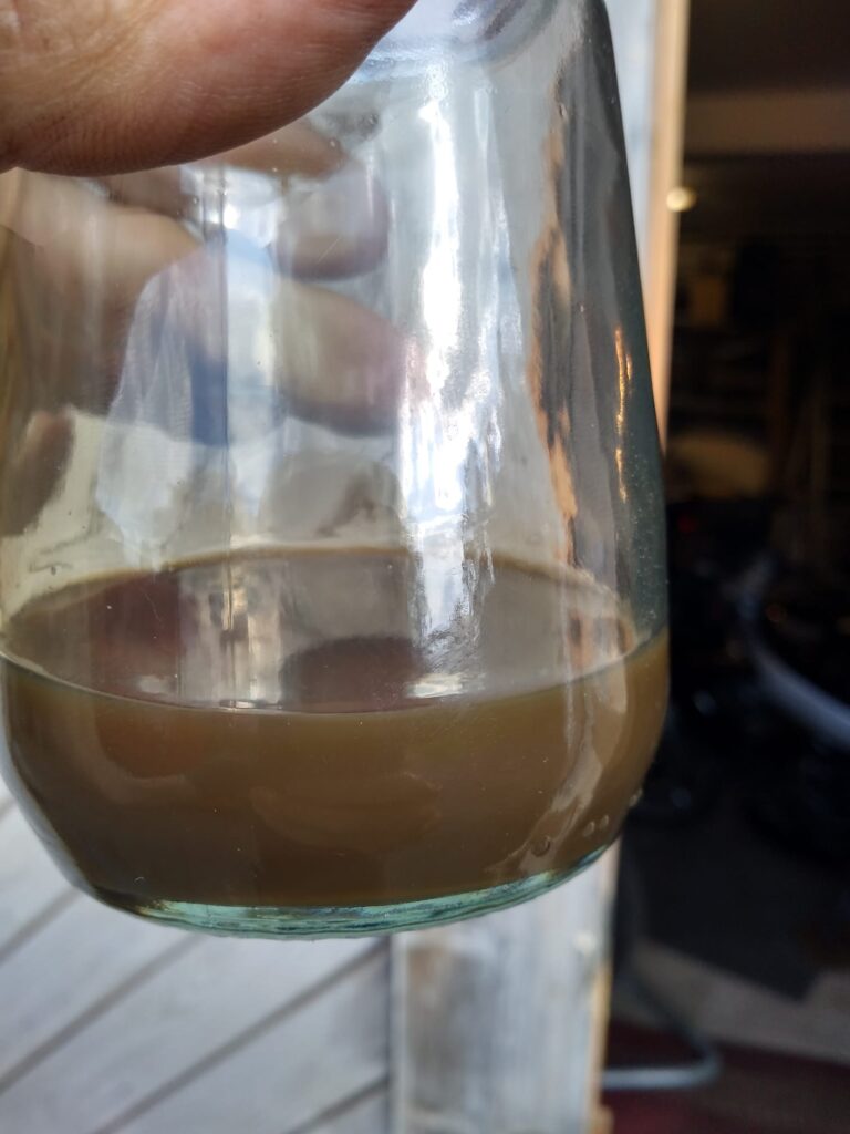
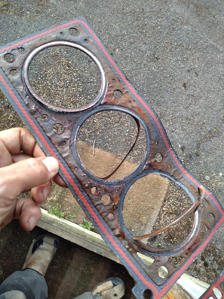
The head gasket upon removal had rust around the cut outs. I can only think that as the head gasket is made out of multiple layers this rusty sweating was a result of the coolant working it’s way between these layers until it reached the outside edge !
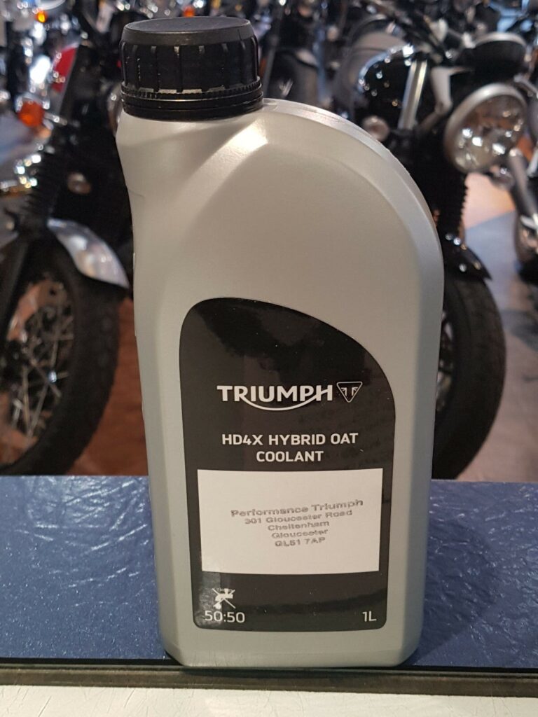
Some research and a bit of head scratching later and I decided the standard coolant wasn’t compatible with the new headgasket materials that Triumph was using. So if you can’t beat them join them sort of attitude I decided to use Triumph Hybred Oat coolant on the rebuild, that way there couldn’t be anything else to point the finger at should it happen again. I also used a little Wellseal compound top and bottom of the gasket for belt and braces !
This is the stuff you want it’s green and you’ll need 3 bottles
It has done thousands of miles now and not a peep of sweating I do believe it’s nailed it 😉